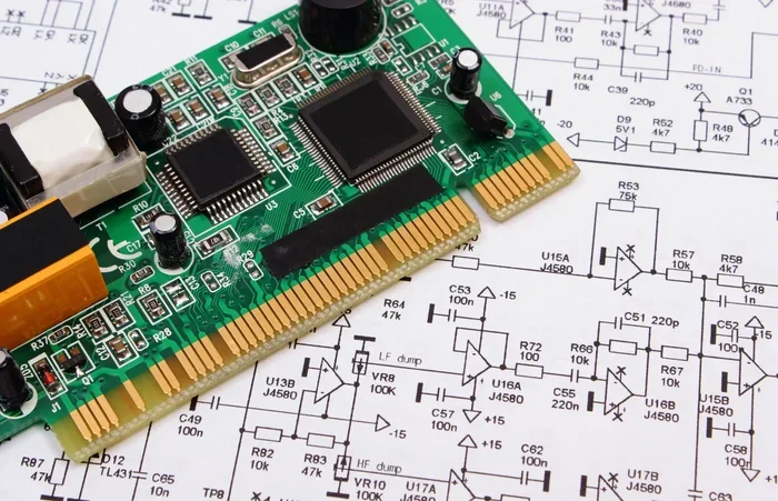

The schematics meaning refers to a visual diagram that represents an electrical or electronic system using standardized symbols and connected lines. These drawings serve as blueprints for building, understanding, and troubleshooting circuits. Whether you are an engineer, a student, or a curious hobbyist, grasping the schematics meaning opens the door to working with electronic devices confidently.
Key Takeaways
- Schematics are visual blueprints: They use symbols and lines to show how electronic components connect and interact within a circuit.
- Reading schematics is a valuable skill: It helps engineers, technicians, and hobbyists design, build, and fix electronic devices efficiently.
- Different types of schematics exist: Circuit schematics, wiring diagrams, block diagrams, and layout schematics each serve a unique purpose.
- Standardized symbols make schematics universal: Resistors, capacitors, transistors, and other components all have recognized symbols across the industry.
- Schematics differ from other technical drawings: Unlike physical blueprints, schematics focus on electrical connections and signal flow, not physical dimensions.
- Common mistakes can be avoided: Paying attention to symbol orientation, ground connections, and net labels prevents costly errors.
- Schematics matter beyond electronics: Fields like plumbing, HVAC, and manufacturing also rely on schematic-style diagrams for system design.
📑 Table of Contents
- What Is the Schematics Meaning?
- Why Schematics Matter in Engineering and Design
- Common Types of Schematics and What They Show
- How to Read a Schematic Diagram Like a Pro
- Essential Schematic Symbols and Notations
- Practical Tips for Working with Schematics
- Schematics vs. Other Technical Drawings
- Conclusion
What Is the Schematics Meaning?
At its core, the schematics meaning is simple. A schematic is a drawing that shows how parts of an electrical or electronic system connect to each other. Instead of showing what something looks like in real life, a schematic shows how the pieces work together electrically. Think of it like a map, but instead of streets and landmarks, you see components and wires.
The schematics meaning goes beyond just lines and shapes. It represents a language that engineers and technicians use worldwide. When you look at a schematic diagram, you are looking at a communication tool. It tells you which component goes where, how signals flow, and what connections matter most. This is why understanding the schematics meaning is so important for anyone working with electronics.
Breaking Down the Term
The word “schematic” comes from the Greek word “schēmatikos,” which means “figure” or “diagram.” In modern use, a schematic is a simplified, abstract representation of a system. It strips away physical details and focuses purely on functional relationships. When people search for the schematics meaning, they usually want to know what these diagrams show and how to read them.
A schematic diagram uses symbols to represent real-world parts. A zigzag line might stand for a resistor. Two parallel lines could mean a capacitor. These symbols are not random. They follow international standards set by organizations like the International Electrotechnical Commission (IEC). This standardization is what makes the schematics meaning consistent across countries and industries.
Why People Search for This Term
Many people look up the schematics meaning because they have encountered a diagram and felt lost. Maybe you opened an electronics kit and found a sheet of paper covered in strange lines and shapes. Or perhaps your job requires you to interpret electronic schematics but you never received proper training. Whatever the reason, the demand for clear explanations of schematics meaning is growing every year.
The rise of DIY electronics, maker culture, and online learning has put more people in front of schematic diagrams than ever before. Hobbyists building Arduino projects, students studying electrical engineering, and professionals designing PCB layouts all need to understand what schematics communicate. Knowing the schematics meaning is no longer just for experts. It is a foundational skill for anyone interested in technology.
Why Schematics Matter in Engineering and Design
The schematics meaning matters because these diagrams are the backbone of modern electronics. Without them, designing a circuit board or fixing a broken device would be guesswork. Schematics give engineers a clear, shared view of how a system should work before any physical building begins. They save time, reduce errors, and make collaboration possible across teams and even across continents.
The Role of Schematics in Circuit Design
When engineers design a new circuit board or PCB layout, they start with a schematic. The schematics meaning in this context is a functional blueprint. It shows every electronic component and every connection point. Engineers use schematic capture software to create these diagrams digitally, and then the software can convert the schematic into a physical PCB layout.
The schematics meaning in circuit design also includes something called a netlist. A netlist is a list of all the connections in the circuit. It tells the manufacturing software which traces to put on the board. If the schematic is wrong, the netlist is wrong, and the final board will not work. This is why understanding the schematics meaning is so critical in the design phase.
How Schematics Help Teams Collaborate
In large projects, many people work on the same product. A circuit design team might include architects, layout engineers, testers, and manufacturers. The schematics meaning acts as a universal reference point. Everyone reads the same diagram and understands the same connections, even if they are in different offices or time zones.
Technical documentation also relies heavily on schematics. When a product needs maintenance or updates years later, the original electronic schematics are often the only complete record of how the system was built. This is why companies invest heavily in creating accurate schematic diagrams and storing them properly. The schematics meaning extends far beyond the initial design phase.
Common Types of Schematics and What They Show
Not all schematics look the same, and not all serve the same purpose. The schematics meaning can shift depending on the type of diagram you are looking at. Let us walk through the most common types so you can tell them apart and know what each one is meant to show.
Circuit Schematics
A circuit schematic is the most common type. It shows the electrical connections between components using standardized schematic symbols. You will see resistors, capacitors, inductors, transistors, and integrated circuits all represented by simple shapes. The lines between them represent wires or conductors. The schematics meaning of a circuit schematic is to show the logical connections, not the physical layout. It tells you what connects to what, but not where each part sits on a board.
Wiring Diagrams and Layout Schematics
A wiring diagram is different from a circuit schematic. While a circuit schematic shows logical connections, a wiring diagram shows the physical path of the wires. The schematics meaning in a wiring diagram is more about real-world placement. You might see wires color-coded, connectors labeled, and components drawn in positions that match their actual locations inside a device.
Layout schematics bridge the gap between circuit schematics and physical boards. They show where components sit on a circuit board and how traces route between them. The schematics meaning here is practical and manufacturing-focused. A PCB layout engineer uses these diagrams to place parts and route copper traces on a real board.
Block Diagrams and Functional Schematics
A block diagram takes a higher-level view. Instead of showing individual components, it shows functional blocks. Each block represents a section of the system, like a power supply, amplifier, or filter. The schematics meaning of a block diagram is to communicate the overall architecture and signal flow. These diagrams are excellent for explaining complex systems quickly, without getting lost in individual component details.
Functional schematics go a step further. They show how signals behave as they move through a system. The schematics meaning here focuses on what each part does, not just how it connects. These are common in technical documentation and educational materials because they help readers understand the purpose behind each section of a circuit.
How to Read a Schematic Diagram Like a Pro
Reading a schematic diagram might seem intimidating at first. All those lines and symbols can look like a foreign language. But once you understand the basic rules, reading schematics becomes much easier. The schematics meaning reveals itself when you learn to follow the flow of signals and power through the diagram.
Start With the Power Source
Every circuit needs power. When you look at a schematic diagram, find the power source first. This is usually marked as VCC, VDD, +12V, 5V, or GND. The schematics meaning becomes clearer when you identify where energy enters the system. From there, follow the lines to see which components receive power and in what order.
Think of it like tracing a river upstream. Start at the point where the river enters the landscape and follow it to see which areas it touches. In a schematic diagram, the “river” is electrical current, and the “landscape” is the collection of components it flows through.
Follow the Signal Path
After finding the power source, trace the signal path. Signals are the information-carrying parts of a circuit. They might be audio, video, data, or control signals. The schematics meaning includes understanding which lines carry signals and which carry power. In many diagrams, signal lines are thinner or labeled with names like “IN,” “OUT,” or “CLK.”
Use your finger or a cursor to trace each path slowly. Do not rush. The schematics meaning will start to make sense as you see how one component feeds into the next. If you get lost, look for labels and reference designators. These are letters and numbers like R1, C2, or U3 that tell you exactly which component you are looking at.
Look for Ground Connections
Ground is the return path for electrical current. In a schematic diagram, ground is usually shown as a series of horizontal lines that get shorter, like a triangle or a set of steps. The schematics meaning includes understanding that every circuit needs a complete path from power to ground. Without a proper ground connection, the circuit will not function.
When reading a schematic diagram, always check that ground connections are present and correct. A missing ground is one of the most common errors in electronic schematics. It can cause a circuit to behave erratically or not work at all. The schematics meaning becomes much clearer once you understand the role of ground in completing the electrical path.
Essential Schematic Symbols and Notations
The schematics meaning relies on a set of standardized symbols. Each symbol represents a specific electronic component. Learning these symbols is like learning the alphabet of the schematic diagrams language. Once you know the basic symbols, you can read most electronic schematics with confidence.
Common Electronic Components
Here are the most common symbols you will see in electronic schematics:
- Resistor: A zigzag line or a small rectangle. Resistors limit the flow of current. They are one of the most common components in any circuit.
- Capacitor: Two parallel lines of different lengths. Capacitors store and release electrical energy. They are used for filtering, timing, and energy storage.
- Inductor: A series of loops or coils. Inductors store energy in a magnetic field and are used in power supplies and filters.
- Diode: A triangle pointing to a line. Diodes allow current to flow in one direction only. They protect circuits and convert AC to DC.
- Transistor: Three lines meeting at a point. Transistors act as switches or amplifiers. They are the building blocks of modern electronics.
- Integrated Circuit (IC): A rectangle with pins on each side. ICs contain thousands or millions of transistors in a single chip.
The schematics meaning depends on recognizing these symbols quickly. When you can identify a resistor from a capacitor at a glance, reading schematic diagrams becomes much faster and more intuitive.
Understanding Lines and Connections
In electronic schematics, lines represent wires or conductors. A line connecting two components means they are electrically connected. If two lines cross without a dot, they are not connected. A dot at a junction means the lines are connected. These small details are part of the schematics meaning and missing them can lead to misunderstandings.
Net labels are another important notation. A net label is a short name written on a line, like “VCC” or “AUDIO_IN.” It tells you that this line connects to another line with the same label, even if they are far apart on the diagram. Net labels make complex schematic diagrams much easier to read because you do not have to trace every single wire across the page.
Practical Tips for Working with Schematics
Now that you understand the schematics meaning and the different types of diagrams, let us talk about how to actually work with them effectively. Whether you are reading a schematic for the first time or creating one for a new project, these practical tips will help you get better results.
Quick Tips for Beginners
If you are just starting out, here are some quick tips to build your skills:
- Start simple. Begin with basic schematic diagrams that have only a few components. A simple LED circuit with a resistor is a great place to start.
- Use color coding. Print your electronic schematics and use colored pens to trace different paths. Red for power, black for ground, and blue for signals works well.
- Refer to datasheets. Every electronic component has a datasheet that shows its schematic symbol and pinout. Keep these handy when reading complex schematic diagrams.
- Practice regularly. The more schematic diagrams you read, the faster you will get. Try reading schematics from old electronics you have lying around.
- Use software tools. Programs like KiCad, Eagle, and EasyEDA let you view, edit, and simulate schematic diagrams digitally. They are excellent for learning.
Common Mistakes to Avoid
Even experienced people make mistakes when working with schematic diagrams. Here are common errors to watch out for:
- Ignoring ground connections: A missing ground connection can cause a circuit to malfunction. Always verify that every component has a proper ground path.
- Misreading symbol orientation: Some components, like diodes and transistors, have a specific orientation. Putting them in backwards will prevent the circuit from working.
- Overlooking floating pins: In electronic schematics, some pins on ICs may be unused. These pins need to be connected properly or they can cause noise and instability.
- Confusing wiring diagrams with circuit schematics: Remember that wiring diagrams show physical layout, while circuit schematics show logical connections. Mixing these up can lead to errors during assembly.
- Skipping the netlist check: Before manufacturing a board, always verify the netlist generated from your schematic diagram. A small error here can mean a wasted board.
Schematics vs. Other Technical Drawings
The schematics meaning is unique, but it is easy to confuse schematics with other types of technical drawings. Understanding the differences helps you use the right type of diagram for the right job.
A blueprint or engineering drawing shows the physical dimensions and layout of a mechanical part or structure. It includes measurements, materials, and tolerances. A schematic diagram, on the other hand, does not care about physical size or shape. It only cares about electrical connections. The schematics meaning is functional, not physical.
A wiring diagram is closer to a schematic but focuses on the physical routing of wires. It shows where each wire goes in the real world. A circuit schematic shows the same connections but in a simplified, abstract way. Understanding this distinction is part of understanding the full schematics meaning.
In electrical engineering, professionals use all three types of drawings together. The schematic shows the logic, the wiring diagram shows the physical connections, and the layout drawing shows the physical placement of components. Together, they form a complete picture of how an electronic system is designed and built.
Conclusion
The schematics meaning is more than just lines and symbols on a page. It is a powerful communication tool that drives modern electronics, engineering, and manufacturing. When you understand what a schematic diagram is trying to tell you, you unlock the ability to design, build, and troubleshoot electronic systems with confidence.
From the basic schematic symbols to the complex PCB layouts that power our devices, the schematics meaning touches every part of the electronics world. Whether you are a student just starting out, a professional working on circuit design, or a hobbyist exploring electronic schematics for fun, taking the time to understand these diagrams pays off in a big way.
Start by learning the common symbols. Practice reading simple schematic diagrams. Gradually work your way up to more complex electronic schematics. Over time, the schematics meaning will become second nature to you. And once it does, you will see the world of electronics in a whole new light. The diagrams that once looked like random shapes will become clear, readable, and useful tools that help you bring your ideas to life.
Frequently Asked Questions
What does the schematics meaning refer to in simple terms?
The schematics meaning refers to a visual diagram that uses standardized symbols and lines to show how electronic components connect and interact. It is like a blueprint for an electrical circuit, focusing on logical connections rather than physical appearance.
Why is understanding schematics important for beginners?
Understanding the schematics meaning helps beginners read, build, and troubleshoot electronic devices. It is a foundational skill that opens up opportunities in electronics, circuit design, and DIY projects. Without this knowledge, working with electronic components becomes much harder and more frustrating.
What is the difference between a schematic diagram and a wiring diagram?
A schematic diagram shows logical electrical connections using abstract symbols, while a wiring diagram shows the physical routing and placement of wires. The schematics meaning focuses on function and connectivity, whereas a wiring diagram focuses on real-world physical layout and wire paths.
Can anyone learn to read schematics, or is it only for engineers?
Anyone can learn to read schematics. The schematics meaning is based on standardized symbols that anyone can study and practice. While engineers use schematics daily, hobbyists, students, and tech enthusiasts also benefit greatly from understanding how to read electronic schematics. Start with simple circuits and build your skills over time.
What software tools are used to create and read schematics?
Popular tools for creating and reading schematic diagrams include KiCad, Autodesk Eagle, EasyEDA, and Altium Designer. These programs allow users to draw electronic schematics, simulate circuits, and convert designs into PCB layouts. Many of these tools are free or offer free versions for beginners.
How do schematics relate to PCB layout and manufacturing?
The schematics meaning serves as the starting point for PCB layout and manufacturing. Engineers create a schematic first, then use it to generate a netlist and physical board layout. The schematic ensures that all electrical connections are correct before any physical board is produced, which reduces costly manufacturing errors.